Worm Gear Data Sheet.55. Worm gear ratio and torque information. View Parts & Specs. About any File Format. Lecture 8 – SPUR GEAR DESIGN. Buckingham design approach for wear strength. GEARS AND GEAR DRIVES 2001 MSD Motion System Design. In worm-gear sets, the worm is most often the driving member. How-ever, a reversible worm-gear has the.


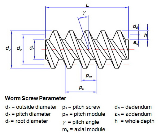
Formulas for gear calculation. To design a gear tooth profile which rolls through the mesh without friction. Formulas for gear calculation - external gears. Download Free Lecture Notes-Pdf Link-IX. A box must contain a worm and a mating gear (helical gear) and normally the axis of the worm is perpendicular to the axis of the gear. If you want to create a high gear ratio, nothing beats theworm gear. In a worm gear, a threaded shaft engages the teeth on a gear. Each time the shaft spins one revolution, the gear moves one tooth forward. If the gear has 40 teeth, you have a 40:1 gear ratio in a very small package. Wormgearsare used when large gear reductions are needed. Are read back on closing the gear calculation. On the page ‘Gear connections' the torque for each gear is shown and its safety factors. Selecting ‘Cylindrical gear pairs' an overview for gear pair data is shown in a table. Graphics for gear pairs Two graphics for gear pairs are available so far. The line load and the gap width. Input Parameters Teeth type - common or spiral Gear ratio and tooth numbers Pressure angle (the angle of tool profile) α Module m (With ANSI - English units, enter tooth pitch p = π m) Unit addendum ha. Unit clearance c. Unit dedendum fillet r f. Face widths b 1, b 2 Unit worm gear correction x Worm size can be specified using the: worm diameter factor q helix direction γ pitch diameter.

To calculate a worm gear with center distance 100 mm. The worm has 2 teeth, and the worm wheel has 41 teeth. The axial/transverse module is 4. The pressure angle at the normal section is 20°. The worm's facewidth is 60 mm. You should select a sensible facewidth for the worm wheel. The axis tolerance is js7.
ZAR3 Worm Gear Calculation ZAR3+ Software for Cylindrical Worm Gear Design (C) Copyright 1993-2017 by HEXAGON Software, Berlin Bases for Calculation ZAR3 calculates all dimensions of cylindrical worm gear pairs with ZI, ZA, ZK, ZN or ZH worms, as well as efficiency, tooth forces and the safety margins against root fatigue fracture and pitting. Pre-dimensioning In pre-dimensioning recommendations are made for axial distance, modulus and number of teeth based on gear ratio, drive power, drive rotational speed and material. The recommendations can be used in the following geometry and strength calculations. Geometry Calculation In dimensioning you can adjust the recommended values to match available sizes or company standards. Or by varying the axial distance ratio and addendum modification you can determine the optimum worm gear for your application.
Strength Calculation The strength calculation computes the factors SF (fatigue fracture) and SH (pitting) along with tooth forces on the worm and worm gear, as well as the efficiency of the gear. Efficiency ZAR3 calculates the toothing efficiency, toothing and idling loss of power. The program provides recommended values and help graphics for determination of the tooth friction value. Material Data Base The program already includes a data base containing the most important gear materials and their values.
Users of the ZAR1+ spur gear and ZAR2 bevel gear programs can access this as a common data base. Tooth Forces Axial and radial forces, as well as tangential force and normal force are calculated. These values can be transfered to the WL1/WL1+ software for shaft calculation. Plus-Version ZAR3+ The extended version ZAR3+ provides additional functions: ZAR3+ generates true-scale drawing of worm and worm gear. Tekken 5 weebly com.
ZAR3+ provides an additional input window for modifications of tooth height factors and profile shift coefficient x. These functions are useful for design of complementary gears of steel worm and plastic worm gear. ZAR3+ calculates tooth thickness and over pin/ball diameters (OPD). You can enter pin diameter and flank tolerances or select from tolerance system according to DIN 3967.

CAD Interface A true-scale drawing of worm and worm wheel, as well as tables with the gear data can be exported to CAD via the DXF or IGES interfaces. The drawings can of course also be displayed on screen and printed out. Import/Export Text printout can be generated as HTML table and exported to Excel. Input data may be loaded from an Excel worksheet.

Formulas for gear calculation. To design a gear tooth profile which rolls through the mesh without friction. Formulas for gear calculation - external gears. Download Free Lecture Notes-Pdf Link-IX. A box must contain a worm and a mating gear (helical gear) and normally the axis of the worm is perpendicular to the axis of the gear. If you want to create a high gear ratio, nothing beats theworm gear. In a worm gear, a threaded shaft engages the teeth on a gear. Each time the shaft spins one revolution, the gear moves one tooth forward. If the gear has 40 teeth, you have a 40:1 gear ratio in a very small package. Wormgearsare used when large gear reductions are needed. Are read back on closing the gear calculation. On the page ‘Gear connections' the torque for each gear is shown and its safety factors. Selecting ‘Cylindrical gear pairs' an overview for gear pair data is shown in a table. Graphics for gear pairs Two graphics for gear pairs are available so far. The line load and the gap width. Input Parameters Teeth type - common or spiral Gear ratio and tooth numbers Pressure angle (the angle of tool profile) α Module m (With ANSI - English units, enter tooth pitch p = π m) Unit addendum ha. Unit clearance c. Unit dedendum fillet r f. Face widths b 1, b 2 Unit worm gear correction x Worm size can be specified using the: worm diameter factor q helix direction γ pitch diameter.
To calculate a worm gear with center distance 100 mm. The worm has 2 teeth, and the worm wheel has 41 teeth. The axial/transverse module is 4. The pressure angle at the normal section is 20°. The worm's facewidth is 60 mm. You should select a sensible facewidth for the worm wheel. The axis tolerance is js7.
ZAR3 Worm Gear Calculation ZAR3+ Software for Cylindrical Worm Gear Design (C) Copyright 1993-2017 by HEXAGON Software, Berlin Bases for Calculation ZAR3 calculates all dimensions of cylindrical worm gear pairs with ZI, ZA, ZK, ZN or ZH worms, as well as efficiency, tooth forces and the safety margins against root fatigue fracture and pitting. Pre-dimensioning In pre-dimensioning recommendations are made for axial distance, modulus and number of teeth based on gear ratio, drive power, drive rotational speed and material. The recommendations can be used in the following geometry and strength calculations. Geometry Calculation In dimensioning you can adjust the recommended values to match available sizes or company standards. Or by varying the axial distance ratio and addendum modification you can determine the optimum worm gear for your application.
Strength Calculation The strength calculation computes the factors SF (fatigue fracture) and SH (pitting) along with tooth forces on the worm and worm gear, as well as the efficiency of the gear. Efficiency ZAR3 calculates the toothing efficiency, toothing and idling loss of power. The program provides recommended values and help graphics for determination of the tooth friction value. Material Data Base The program already includes a data base containing the most important gear materials and their values.
Users of the ZAR1+ spur gear and ZAR2 bevel gear programs can access this as a common data base. Tooth Forces Axial and radial forces, as well as tangential force and normal force are calculated. These values can be transfered to the WL1/WL1+ software for shaft calculation. Plus-Version ZAR3+ The extended version ZAR3+ provides additional functions: ZAR3+ generates true-scale drawing of worm and worm gear. Tekken 5 weebly com.
ZAR3+ provides an additional input window for modifications of tooth height factors and profile shift coefficient x. These functions are useful for design of complementary gears of steel worm and plastic worm gear. ZAR3+ calculates tooth thickness and over pin/ball diameters (OPD). You can enter pin diameter and flank tolerances or select from tolerance system according to DIN 3967.
CAD Interface A true-scale drawing of worm and worm wheel, as well as tables with the gear data can be exported to CAD via the DXF or IGES interfaces. The drawings can of course also be displayed on screen and printed out. Import/Export Text printout can be generated as HTML table and exported to Excel. Input data may be loaded from an Excel worksheet.
HEXAGON Help System For all entries a help text or auxiliary picture can be displayed. For example, there are diagrams for input of the tooth friction value µz0 in relation to lubricant and average slide speed. There are also diagrams for optimizing the diameter-to-center distance ratio dm1/a in relation to fatigue stress or efficiency. Users can modify and append help texts and auxiliary pictures. When error messages occur you can have an error description and remedy suggestion displayed.
Hardware and Software Requirements ZAR3+ is available as 32 bit and 64 bit application for Windows 7, Windows 8, Windows 10. Scope of Delivery CD-ROM or zip file for download with program and pdf manual, License agreement for indefinite period of time. Information and Update Service HEXAGON Software is continuously improved and updated. Licensed users can obtain new versions at the update price.
Worm Gear Design Calculation Pdf Free
Worm Gear Design Calculation Pdf Files Pdf
Worm Gear Design Calculation Pdf Download
Each program is provided with an individual license number and user files. No extra charge is made to registered users for telephonic support and hotline use.
